Improve the efficiency of SolidWorks drawing
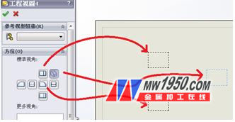
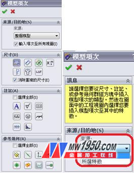
Some users do not use SolidWorks drawings. It may be that after creating the views in Solidworks, they are saved as *.DWG to the 2D CAD interface of the custom operation. However, sometimes there are compatibility problems, it takes time to modify. . Therefore, in this chapter, the author hopes to bring users the information to improve the efficiency of the drawing operation, that is, directly use SolidWorks to output the engineering drawing, which can bring many benefits such as improving drawing speed, data synchronization, and reducing error rate. First, in the pre-operation, the user must prepare a set of template files belonging to the company, including parts, assemblies, drawing templates, attribute label template files, part form template files, and so on. If the above templates are available, the next view and dimension will be created by the Solidworks drawing. Before generating the view, there is a trick that is "preset view". Can you check if the drawing template is set? There are some parts of the drawing, which may often only require a front view and a top view... and so on. The default view can be used to pre-position these views when creating a drawing view. This function can be found in the drop-down menu > Insert > Drawing View > Predefined View (Figure 1). After placing the predetermined position, you can set this. The perspective to be placed in the future (Figure 2) can be saved as a drawing template file *.drwdot after setting. (figure 1) (figure 2) After the view is generated, the most important thing is the dimensioning. How to quickly mark it out, the user can use the "model item" in the annotation function (Fig. 3). This function can be used by the engineer during the construction of the part. Draw the marked drive size or the parameter size that will be generated when the feature is generated. In this way, you don't have to manually mark one size, and the model item is used to indicate the "drive size". In the direct modification of the size, the related view will be changed synchronously with the model (Figure 4). After executing the "model item", the source option can select "whole model" or "selected feature" (Figure 5). The simpler model can be entered as "whole model". If it is a more complex model, consider "selected." Feature", click on the feature line segment on the view to generate the size. If you encounter the automatically generated size to move to other views, you can move it by holding down the "Shift" button on the keyboard, and other views. Also need the same size, hold down the "Ctrl" drag to copy the size to other views, so the size is also quite flexible. (Image 6) (image 3) Figure 4, 5 (Figure 7) (Figure 8) How to quickly set the size format, you can now use the size palette (Figure 7) to produce the size palette, you can immediately apply and modify the dimensional tolerances. Accuracy, annotations, styles, etc. (Figure 8), In addition, you can also add the common size format setting to "style", which will be quite convenient when you want to use it later. You can select multiple styles at the same time (Figure 9). (Figure 10) Next, the engineering drawing has another important point, that is, the field information on the frame. As long as the drawing template has the text link attribute, the view will automatically generate the text, and the part information will be completely synchronized. Avoid manual input leading to errors and greatly reduce the chance of errors (Figure 11). (Figure 11) It is also possible to use the relevant form template, such as the parts list, through the first inserted part table, configure the information fields that belong to the company, press the right mouse button on the form > Save as (Figure 12) Save it as a part form template (Figure 13), and use it in the future. You don't have to set it every time. (Figure 13) Finally, by the way, 2013's new features "Save View" and "Convert to Sketch", you can now click on a single view, go to Properties Manager > Save View to DWG/DXF (Figure 14) instead of You can save the DWG/DXF file by saving the output of the drawing. This new function is very convenient for users who are doing sheet metal processing. If you only need to output the expansion drawing, the "convert to sketch" can let the user edit directly on the drawing. Contour, in the view, press the right mouse button to convert to a sketch (Figure 15), the system automatically converts the contour into a line segment (Figure 16), the user can quickly modify the contour, for example: rounded corners changed to right angles, but the view and The link to the model will be broken. (Figure 14) (Figure 16) The techniques described above, if the user can fully plan to use the file template, I believe that it will save a lot of time when generating the drawing, and bring many benefits, which can help users to import SolidWorks initial planning, in order to benefit future Improve the efficiency of drawing drawings, so generating drawings can be very simple and fast. About Shiwei Established in 1997, Shiwei International (Taiwan stock code: 8416), with complete product lines such as CAID, CAD, RP, RE, CAE, CAM, PDM, cooperates with consulting and customized services, and provides R&D, design and manufacturing. Complete solution. Rich tutoring experience, coupled with high-quality software and hardware, and senior team consulting and training courses, has so far coached more than 5,000 companies in Taiwan and mainland China, providing solutions to customer needs and helping the industry to enhance competitiveness. Shiwei International Headquarters is located in Neihu, Taipei, and has service bases in Hsinchu, Taichung, Tainan, Kaohsiung, Shanghai, Dongguan, Ningbo, Tianjin, Jinan, Nanjing, Suzhou, Xiamen and Shenzhen. 5.29~6.7, participate in the 2013 SolidWorks Solution Day, and Shiwei will solve your problems in 9 major cities! Event registration: http:// Indoor Rental LED Screen Display,Indoor Stage Rental LED Display SHENZHEN YGHQ Optoelectronics Co.,ltd. , https://www.leds-smd.com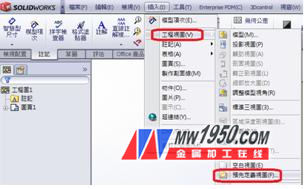

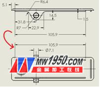
(Image 6) 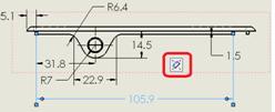

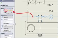
(Figure 9) 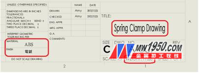
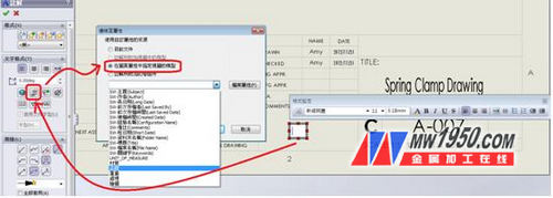
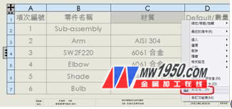
(Figure 12) 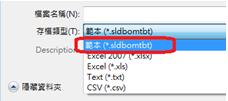
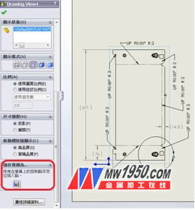
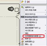
(Figure 15) 

