Not just a problem with Simulation
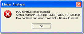
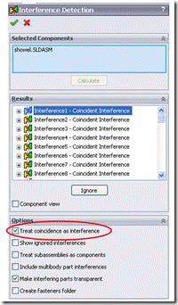
Usually the analysis problems encountered are relatively easy to solve, most of them are input parameter problems. If the model fails to mesh successfully, you will think, is the grid too thick, or whether all the parts are combined correctly, or Did you choose the correct solver? But one of the key points of a successful analysis is the model itself. Modeling the model without analytical intent can be a critical issue. A good example is that if the analysis model is created by someone else using other CAD software or when building the model without considering how to assemble for analysis, the model problem will be highlighted. I encountered this type of problem when I was working on a model from other CAD last week. The model looks fine and can be meshed, but I encountered the following error when solving: Through the tool-interference check, select the assembly and click Calculate to check the model's interference problem. SolidWorks will list the relevant interference information for viewing. A single line appears in three places, which is also considered to be interference between two parts. As you can see in the figure below, you will see red thick lines when inspecting, which is different from the other faces. No matter how you zoom in on this area, it will not appear as a typical area. To solve the problem, all the individual entities are merged to create a combined entity, and all the contact faces can be combined to transfer the load without the need to make contact definitions. The moral of this story is that doing simulation requires a solid foundation work. Don't forget to check the consistency of the CAD model, especially for models that were not built for analysis.
LEDER technology`s mirror with light which has the sleek linear profile creates a perfect, contemporary backdrop for unique glass options. Tiles of either clear crackle glass or clear staggered rock glass are set in an organic version of a subway tile look and allow the LED light to shine through, adding rich sparkle to the room. Fixtures have a CCT of 3000K.
With its unique circular, movable lights, this vanity light allows you to customize your bathroom lighting to focus on the areas that need it the most.A vanity light like this two-light piece is perfect for crowning your sink and mirror combo, casing illumination down on your while you prep for your day. Crafted from a slim metal mount , this piece features three streamlined holders with clear glass cone shades that lend it a sleek, modern look.
Features:
• Unique design
• Good waterproof performance
• Artificial Intelligence Technology
• Energy conservation
• Easy installation and maintenance
• Color temperature :3000k-6000K
• The price is reasonable and satisfactory
• Type of protection: IP20
• Warranty for bulbs :2 years
And since it's designed for damp spaces, you can take that extra-steamy shower without worrying.These mirrors undergo rigorous testing to ensure their quality and longevity.Simply touch the square button for 3 seconds to change light intensity from normal to brightest. The mirror has a memory function.
We have rich production experience in lighting.Except Decoration Lighting , we also offered other product in Indoor Lighting .Such as :
LED Panel Light , Track Light , Linear Light ,Wall Light , LED Strip Light , LED Tube Light , Cabinet Light , LED Bulb , LED Ceiling Light as so on .
Light Up Vanity Mirror,Best Makeup Mirror,Light Up Makeup Mirror,Diy Vanity Mirror JIANGMEN LEDERLIGHT LIGHTING Co.,LTD , https://www.wallwasherlights.com
The problem is obviously that there are parts that do not have the correct constraints (error prompts), resulting in rigid body displacement.
You can usually try to find a problem by running a frequency analysis on the same model. Frequency analysis can help us find parts or entities with rigid body displacement. However, in this model, the frequency analysis also gives an error message and cannot be completed normally. 
After checking the settings of the analysis model again and again, I finally found the geometry in question. The reason is that there is an error in the data conversion between different CAD software. It is difficult to import the model from other software to complete the global combination setting through SolidWorks. 
The "coincidence is interference" option, if selected, may have a lot of interference, and when it is not selected, there may be no interference, then the globally defined contact definition is applied to this type of interference. This is what happened in my model, but the analysis was still unsuccessful. Then you need to find one in the interference check to find and finally find the problem. 
Obviously, the geometrical area combination indicated by these thick lines also needs to be applied. This will cause the singularity of the stress and lead to infinity, which we don't want.
