Analysis of Difficult Machining Process of Five Key Parts of Automobile Engine

Source: Metal processing WeChat, please indicate if you reprint.
The engine is the "heart" of the car. The development of the car has a direct relationship with the progress of the engine. The engine is mainly composed of five key components, including the cylinder block, cylinder head, crankshaft, camshaft, connecting rod, etc., so these core components Processing has become the key to the manufacture of automotive engines.
Cylinder block

As the core component of the engine, the cylinder block and cylinder head are the must-have items for almost all engine manufacturers. At present, the general trend of machining development of box parts such as cylinders and cylinder heads is that the flexible production line consisting of CNC machine tools and machining centers gradually replaces the rigid production line based on combination machines. In order to meet the needs of mass production, a flexible processing system (FMS) consisting of a convertible box flexible manufacturing unit (FMC) and multiple machining centers has been developed to meet the needs of different varieties and batches of manufacturing. With the promotion of CNC control systems and the development of new tool materials, high-speed modular machining centers made breakthroughs in the 1990s, and flexible machining systems consisting of high-speed machining centers have been widely used in actual production.
The cylinder block is the main bearing for all the parts. The common structure of the cylinder block is an approximate hexahedral box structure with thin walls, more processing surfaces and more holes. It is a typical box body part, mainly processed with cylinder holes and main Bearing holes, camshaft holes, etc., there are a variety of holes, such as lubricating oil passages, cooling water passages, mounting screw holes, etc. There are a variety of couplings, sealing bosses and facets, and their machining accuracy directly affects the assembly accuracy and work of the engine. Performance, at the same time, in order to improve the rigidity and strength of the body, there are also many reinforcing ribs.
Cylinder hole machining: It is processed by rough, semi-precision and fine boring. Machining of the main bearing hole: Generally, the rough machining semi-circular hole is used, and then combined with the camshaft hole and the like. Machining of the camshaft hole: Generally, it is rough, and then combined with the main bearing hole and so on. Machining of tappet holes: Generally, drilling, expanding (é•—) and reaming are used. Processing of the main oil passage hole: The traditional processing method is to use the twist drill for the graded feeding method, which has poor processing quality and low production efficiency, and the current process often uses gun drill for processing.
2. Cylinder head

The shape of the cylinder head is generally a hexahedron, which is a porous thin-walled member, which has a valve seat hole, a valve guide hole, various light holes and threaded holes, a cam shaft hole and the like. The gasoline engine cylinder head has a spark plug hole, and the diesel engine cylinder head has a fuel injector hole.
According to the number of cylinder heads on one engine, it can be divided into integral cylinder heads and split cylinder heads. A single cylinder head that covers only one cylinder, a block cylinder head (usually two cylinders and one cover, three cylinders and one cover) covering more than two cylinders, and an integral cylinder head covering all cylinders (usually Four cylinders and one cover, six cylinders and one cover)
The plane machining of the cylinder head is generally carried out by milling with a machine-clamping cutter. The hole system is generally drilled, expanded and hinged by a radial drilling machine, a combination machine, a machining center, etc.; the conduit and the valve seat are frozen or at room temperature. The press-fit method is used for press-fitting, and the displacement-pressure control method is generally used to control the assembly process in the normal temperature press-fit process.
3. Crankshaft

The crankshaft is the central part of the automobile engine. It is subjected to repeated bending and torsional loads in the engine. Therefore, most of them are destroyed by fatigue fracture or eccentric wear and wear faster, which is an important part affecting the life of the engine. However, its shape is relatively thin and long, and it is easy to deform. The connecting rod neck and the main journal are not on the same axis, which is easy to produce imbalance during processing. Therefore, the numerical control machining of the crankshaft is compared with the machine tool equipment and the numerical control software. Strict requirements.
The central hole of the crankshaft is an important positioning reference for the crankshaft machining process. The common central hole machining method of the crankshaft is the geometric center hole and the mass center hole.
The crankshaft has high technical requirements. The journal diameter tolerance is generally IT6 tolerance, and the journal surface roughness is Ra0.4~Ra0.2μm. Therefore, in order to ensure product quality requirements, the crankshaft must be applied to all journals after rough machining. Finishing of grinding to improve journal accuracy and reduce surface roughness. The traditional grinding method of crankshaft journals is divided into two stages: semi-finishing and fine grinding. However, with the development of blank manufacturing technology and the improvement of roughing equipment processing precision, most of the crankshaft processing plants have cancelled the semi-finishing process. This can shorten the machining process of the crankshaft and reduce the production cost of the crankshaft.
The oil hole of the crankshaft generally has a small hole diameter and a deep depth. It is a deep hole machining, so it is difficult to process. The crankshaft oil hole machining has been gradually processed by gun drilling. The depth of the drill hole used to machine the deep hole can generally be achieved. More than 100 times the diameter, the precision of the gun drilling process can be very high, and the high precision hole can be processed at one time depending on the material to be processed and the different cutting amount.
In order to improve the strength of the crankshaft and increase the wear resistance of the surface, the crankshaft generally needs to strengthen the surface of the journal, the rounded corners, etc. The commonly used strengthening processes include quenching, rolling, nitriding, etc., due to the wide range of quenching and high efficiency. The strengthening effect is good, so quenching has become the main strengthening process at present.
4. Camshaft

The camshaft is an important component in the engine air distribution mechanism. During the engine working cycle, it properly controls the opening and closing time and opening and closing of the intake and exhaust valves, so that the compressed fuel mixture is fully combusted and the piston is pushed. Doing work, then exhausting the exhaust gases out of the combustion chamber, so it affects the power, economy and emissions of the engine. The camshaft belongs to the slender shaft type, which is poor in rigidity and easy to deform. To accurately control the timing of opening and closing of the intake and exhaust valves of the engine, the cam should have high contour accuracy, phase angle requirement, good wear resistance and overall rigidity. . Therefore, the machining of the journal and cam becomes the focus of the entire camshaft machining process, and the machining is often combined with turning, milling and grinding processes and surface strengthening (quenching, shot peening, nitriding) and other auxiliary processes.
The traditional machining process of cam journal: profiled multi-tool car → rough grinding → quenching → semi-finishing, fine grinding → polishing by die belt, current machining process: CNC milling without external mold milling machine → quenching → CNC no Grinding cams → flexible polishing cams by CBN grinding wheel.
One of the revolutionary new technologies that must be mentioned when it comes to camshafts is the assembled camshaft. Compared with the traditional integral camshaft, it has the advantages of light weight, low processing cost and reasonable material utilization.
The assembled camshaft is made by optimizing the material of the cam, the hollow shaft body and the supporting journal, respectively, and separately precision machining, and then assembling by some connection. The cam is generally made of carbon steel or powder sintered material, and the shaft body is The hollow seamless steel pipe is adopted, and the carbon steel cam is formed by cold and warm forging, and is subjected to high-frequency quenching or carburizing treatment. The cam can also be sintered by the powder sintering material through the precision sintering forming technology, and the aluminum alloy is used as the shaft body.
The main process of the assembled camshaft includes press-fit cam → straightening → machining the center hole at both ends → axle neck → grinding journal → grinding cam → cam quenching → deburring → straightening journal → cam journal and cam polishing → cleaning → Comprehensive testing.

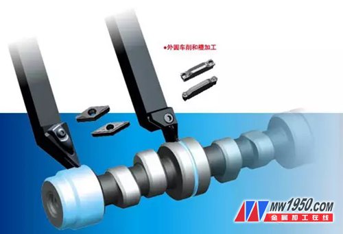
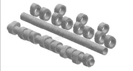
Assembly camshaft schematic
5. Connecting rod
The connecting rod is a power function that connects the piston to the crankshaft. The small end of the connecting rod is connected to the piston through a piston pin, and the big end of the connecting rod is connected to the connecting rod journal of the crankshaft. And the gas pressure of the piston is transmitted to the crankshaft, so that the reciprocating motion of the piston is converted into the rotational motion of the crankshaft.

The shape of the connecting rod is irregular and complicated, and it is difficult to achieve positioning. The size of the connecting rod is a slender shaft connection, which is easy to deform; dimensional tolerance, shape tolerance, surface roughness and the like are relatively high. The processing of the connecting rod follows the principle of the first and second holes, and the other principles after the benchmark. The connecting rod is a relatively rigid part, so the positioning and clamping should reduce the influence of deformation on the machining accuracy.
The connecting rod breaking processing technology (also called connecting rod cracking) is a new manufacturing process and is gradually applied to large-scale production. The cracking of the connecting rod is a new technology for the chipless fracture and splitting of the joint surface of the connecting rod and the connecting rod cover. It has the characteristics of novel concept, economical operation and remarkable benefit.
The main features of the process are:
(1) Processing of large holes. The conventional process generally involves broaching the large hole after cutting, or processing it into an elliptical shape before cutting, because it is intermittent processing, the vibration is large, the tool wears fast, and the tool consumes a large amount. The breaking process processes the large holes into a circular shape.
(2) The connecting rod body and the cover are separated. The conventional process uses a pull-off (or milling, sawing) method, and the breaking process is to break after the bolt hole is processed. After the breaking process, the connecting rod and the separating surface of the connecting rod cover are completely meshed, which improves the joint quality of the connecting surface of the connecting rod cover and the connecting rod, so the separating surface does not need to be broached and ground. Since the separating surface is completely meshed, it is not necessary to add additional precise positioning when assembling the connecting rod and the connecting rod cover, such as bolt hole positioning (or positioning ring hole), as long as the two bolts are tightened, thus eliminating the bolt hole. Finishing.
(3) Processing of joint surfaces. The traditional process is to grind the joint surface after the break, and the assembly position of the link body/cover is positioned by the positioning hole of the two bolt holes and the positioning portion of the bolt, so the perpendicularity of the bolt hole and the separation surface thereof And the center distance dimension of the two bolt holes has strict requirements. The dimensional error causes residual stress to remain in the connecting rod assembly after the connecting rod and the connecting rod cover are assembled.
(4) Bolt hole machining. The assembly position of the connecting rod body/cover of the breaking process is positioned by the rising section, and the assembly position of the connecting rod body/cover of the traditional process is matched by the positioning hole of the two bolt holes and the positioning part of the bolt. To locate, the accuracy requirements for bolt holes and bolts are high. When the connecting rod is processed by the breaking process, the precision requirement is greatly reduced, and the two bolt holes can be processed at different times, thus creating convenient conditions for multi-variety processing. After the big hole of the connecting rod adopts the breaking process, the separating surface of the connecting rod is the most complete meshing, so there is no influence of the separation surface and the machining error of the bolt hole.
(5) Bolt assembly. Bolts are fed, mounted, and mounted on rack-mounted mounting brackets and hydraulically driven vertical slides through bolt feeders with vibrating hoppers, separators, and feeders with conduits and nozzles. The BOSCH tightening machine is pre-tightened. When tightening to a certain set torque, loosen the bolts by means of a device with a waiting function, clean the joint surface, and finally tighten the bolts to the requirements.
Connecting rod breaking technology In the history of connecting rod processing, the invention of the breaking process has epoch-making significance. At present, the connecting rod breaking process has been widely used in China. Shanghai Volkswagen, FAW Volkswagen, Brilliance and Chery have adopted this kind of connecting rod technology, and some professional connecting rod manufacturers have begun to adopt this technology. Domestic equipment manufacturers have already produced related special equipment.

Other LED Solar Light

Solar Light outdoor flood led ,Solar Floodlight,Solar Garden Light,Solar Street Light

Shenzhen You&My Electronic Technology Co., Ltd , https://www.szyoumy.com