Connecting rod bushing hole and big hole processing technology (2)
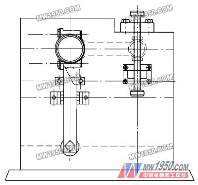
3. Improvement of process tooling In summary, the main reason for the distortion of the connecting rod size head hole parallel and the center distance can not reach the technical requirements is: 1 positioning standard can not ensure coincidence with the measurement reference. 2 secondary clamping produces cumulative error. 3 The workpiece clamping direction is consistent with the thermal expansion direction of the hoe. In this regard, the craftsmanship is improved as follows: (1) For the processing of the large hole and the bushing hole, one boring is completed to ensure the stability of the twist parallel, and the cumulative error caused by the secondary clamping is eliminated. (2) Re-making the fixture so that the thermal expansion of the hammer is not in the same direction as the center-to-center direction of the connecting rod. As shown in Figure 3. To ensure the accuracy requirements of the connecting rod products, the specific operations are as follows: (1) In order to ensure the accuracy of the shape and position of the boring head and the fixture, it is necessary to ensure that: 1 fixture must adjust the straightness in the vertical and horizontal directions on the rail bed to within 0.005 mm. 2 The straightness in the vertical and horizontal planes of the boring head and the fixture is adjusted within 0.005 mm. (2) In order to ensure the coaxiality between the boring head and the connecting rod, the small head hole locating hole must be used for boring the head body boring hole, and the positioning sleeve is added for positioning the shaft positioning. image 3 (3) Due to the diversification of products, the size of the head and the hole are different, the cutting amount can be determined according to the size of the hole diameter. The process parameters during the boring test are: the spindle rotation speed is 800~1400r/min when the large head diameter is Φ60~Φ75mm, cutting The speed is 184 to 186 m/min and the feed rate is 0.02 mm/r. When the large head diameter is Φ45 to Φ60 mm, the spindle rotation speed is 1000 to 1600 r/min, the cutting speed is 100 to 144 m/min, and the feed rate is 0.02 m/r. (4) In order to ensure the cylindricity and surface roughness of the size of the head and the hole, and to facilitate boring, it must be equipped with high-precision boring head, and ensure its lubrication, properly adjust the tightness of the transmission tape, as far as possible to ensure the smooth operation of the transmission Next, increase the rigidity of the boring boring bar. Reasonable use of the geometry of the cutter head and the sharpening head. (5) In order to ensure the twist parallel, take the large end face as the main positioning reference, and the small head adopts the floating screw positioning, as shown in Figure 3 (the screw tightening force is moderate to avoid deformation), the center line of the two screws must be consistent (the small end face and Positioning sleeve distance is 0.2~0.5mm). (6) In order to ensure the verticality of the large end face to the aperture, the large positioning plate is no longer screw-fastened. The large-headed hoe is boring and fixed with a fixed sleeve, and is assembled by cold pressing. The three-point active positioning is used for pressing, and the distance between the positioning sleeve and the pressure plate is adjusted by screws. (7) When adjusting the center distance, fix it with bolts to ensure its accuracy. In summary, since the big hole is used as the first reference, the positioning of the fixed sleeve by the self-boring ensures the verticality of the end face of the big hole to the aperture, and the boring of the large hole and the bushing hole is completed once, and the entire hole is completely ensured. The twisting parallel precision of the connecting rod and the two boring heads are parallel boring. After adjusting and tightening, the center distance can also stably control the dimensional accuracy. After the above process improvement, after processing and testing, 100 pieces of connecting rods were taken to obtain the following data: 1 twisted parallel qualified 99, the pass rate was 99%. 2 The sampling center is 100 qualified, and the pass rate is 100%. 3 The cylindricity, aperture and surface roughness of the large head holes meet the processing accuracy requirements. This process fully meets the processing accuracy requirements of the product and is suitable for mass production. Previous page Pneumatic Seals can sometimes be confused for hydraulic seals because of their similar seal profile. The key difference being, Pneumatic seals are being actuated using compressed air. The air for Pneumatic seals are filtered to remove contaminants that may cause corrosion to the cylinder. Pneumatic seals are generally used in high-speed applications where there are high temperatures. Air Cylinder Seals, Pneumatic Air Cylinder Seals, Pneumatic Cylinder Seal, Pneumatic Cylinder Piston Seals NINGBO BRANDO HARDWARE CO.,LTD , https://www.brandopneumatic.com
BRANDO manufactures the widest range off Pneumatic rod seals, Pneumatic wiper seals or the combinations of the both Pneumatic wiper and rod seal in one, Pneumatic scraper seals and Pneumatic Piston seals.
