Experimental Study on Fuel Quantity Control of Pump Nozzle Diesel Engine
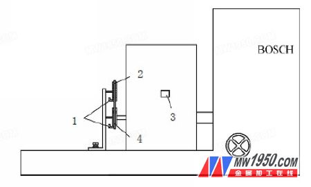
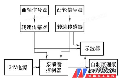
The test device (see Figure 1) includes pump nozzle diesel ECU controller, self-contained principle pump, BOSCH pump test bench, Tektronix TDS3054B oscilloscope, dedicated crank signal panel, dedicated camshaft signal panel, Hall speed sensor, Hall current sensor and 4 NIC -K240 Chaoyang power supply, etc. The self-made principle pump and the crank signal plate and the camshaft signal plate are mounted on the pump test stand, and the rotational speed sensor is installed in the same direction and model. The connections of the controller, solenoid valve, oscilloscope, sensor, power supply and current transformer are shown in Figure 2. 7) On the pump table, turn the camshaft and adjust the top of the screw by the taper side rocker arm with the dial gauge. The starting point of the lift is the base point. We carry high quality Speed Governor as below Passenger Elevator Speed Governors, Panoramic Elevator Speed Governors, Home Elevator Speed Governors, Hospital Bed Elevator Speed Governors, Freight Elevator Speed Governors, Car Elevator Speed Governors, Service Elevator Speed Governors, Goods Elevator Speed Governors, MRL Elevator Speed Governors for all major elevator and escalator brands as below OTIS Elevators, ThyssenKrupp Elevators, Sch****** Elevators, KONE Elevators, Mitsubishi Elevators, Fujitec Elevators, Hitachi Elevators, Toshiba Elevators, Fuji Elevators, Express Elevators, Sigma Elevators, LG Elevators, Hyundai Elevators, BLT Elevators, CANNY Elevators, SJEC Elevators, KOYO Elevators, IFE Elevators, Thyssen Elevators, GiantKONE Elevators, XJ Sch****** Elevators, Xizi OTIS Elevators, Shanghai Mitsubishi Elevators, GUANGRI Elevators OTIS Elevator Overspeed Governor, Thyssen Elevator Overspeed Governor, KONE Elevator Overspeed Governor, GiantKONE Elevator Overspeed Governor, ThyssenKrupp Elevator Overspeed Governor, Sch****** Elevator Overspeed Governor, XJ Sch****** Elevator Overspeed Governor, Xizi OTIS Elevator Overspeed Governor, Mitsubishi Elevator Overspeed Governor, Shanghai Mitsubishi Elevator Overspeed Governor, Fujitec Elevator Overspeed Governor, Hitachi Elevator Overspeed Governor, Toshiba Elevator Overspeed Governor, Hyundai Elevator Overspeed Governor, LG Elevator Overspeed Governor, Sigma Elevator Overspeed Governor, Express Elevator Overspeed Governor, GUANGRI Elevator Overspeed Governor, FUJI Elevator Overspeed Governor, BLT Elevator Overspeed Governor, CANNY Elevator Overspeed Governor, SJEC Elevator Overspeed Governor, KOYO Elevator Overspeed Governor, IFE Elevator Overspeed Governor We also offer multinational corporation with different overspeed governor as below trip speed governor, bail type governor, horizontal shaft governor, pull through governor, centrifugal governor, centrifugal type governor, flyball governor, tail rope governor, displacement governor, displacement type governor, governor safety fence, governor overspeed switch, governor tripping speed, governor catch, governor bracket, governor rope grip jaw, governor switch, governor rope, governor cable, rope retaining guard, governor sheave, governor rope tension sheave, governor tension sheave, governor rope releasing carrier, governor tension weights, wedge type governor, disk type speed governor, escalator overspeed governor, Elevator Speed Governor, Elevator Overspeed Governor, Elevator Governor Elevator Speed Governor,Elevator Overspeed Governor,Over Speed Control Governor,Passenger Elevator Overspeed Governor, Elevator Governors CEP Elevator Products ( China ) Co., Ltd. , https://www.zjelevatortravelingcable.com
This project pump nozzle for diesel engines designed to MPC563 microprocessor of the ECU electronically controlled, power-driven on the circuit design, signal acquisition, the power supply and a CPU peripheral circuits are integrated to the solenoid valve High pressure dual power drive, the software The design uses the program to separate from the MAP data, and the control strategy uses open-loop control. In order to verify the hardware driving capability and software control function of the ECU, and to obtain the oil quantity characteristics related to the engine control, the oil of the pump nozzle solenoid valve is studied in the oil pump test bench. The quantity control feature is necessary.
Test principle and test device
Test principle
The pump test bench set speed is equivalent to the engine working speed, the controller outputs a certain pulse width, and the pump tester has a self-contained principle. The pump injector will spray a certain amount of oil, which converts chemical energy into mechanical energy after the engine is burned, and outputs A certain speed and torque. The engine is mainly used for power generation. The characteristic speed is 800r/min, 1000r/min, the injection advance angle is 36°~-8°, and the interval is 6°. The fixed advance angle is 6° from small to large. Evenly change, measure the oil quantity data until the oil quantity no longer increases with the increase of the pulse width. Draw these sets of data in the same coordinate system to form the fuel injection characteristic curve and study the injection waveform of the solenoid valve. Can be observed by an oscilloscope.
The rotational speed, advance angle and pulse width are fixed by the characteristic values, respectively changing the solenoid valve opening current, maintaining current, opening current working time and high voltage charging current. According to the fuel injection control law, the corresponding test waveform and the characteristic curve spectrum, the corresponding values ​​are obtained. The parameters that the driver circuit needs to set.
2. Test device installation 
Figure 1 test installation
1. Speed ​​sensor 2. Crank signal plate 3. Oil outlet 4. Cam signal plate
3. Test system connection 
Figure 2 Control system connection
4. Pump nozzle box and phase adjustment
The cam crankshaft phase relationship is shown in Figure 3. The angles are calculated as follows:
1) The pump table faces the output shaft clockwise.
2) The cam base circle and the key are at an angle of 90°.
3) The working angle of the cam profile is 20° cam angle, and the working starting angle is 21.5° with respect to the base circle.
4) The base circle corresponds to the critical point of the roller corresponding to the pump dial 205°.
5) The cam profile corresponds to the starting point of the fuel injection operation of 226.5°.
6) The virtual top dead center is 5° cam angle according to the base circle advance top dead center, corresponding to the pump dial 231.5°.
