Five-axis machining application challenges (Figure)
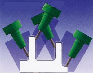
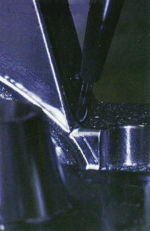
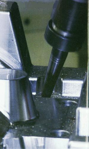
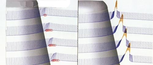
Figure 1 Three-axis machining path (Image courtesy of Sescoi) When using shorter tools, the spindle should be tilted to ensure that special areas of the workpiece can be machined. 3+2 axis machining is generally considered to be a constant angle to the spindle. Complex workpieces may require many oblique views to cover the entire workpiece, but this can result in overlapping tool paths, which increases machining time. Figure 2 3+2 axis tool path In order to overcome the shortcomings of 3+2 axis machining, five-axis simultaneous machining may be a better choice, not to mention that some five-axis machines also have some features specifically designed for the mold industry. Five-axis simultaneous machining can coordinate three linear axes and two rotary axes to make them move at the same time, solving all the problems of three-axis and 3+2-axis machining. The tool can be very short, no view overlap, and missing machining area. The possibility is smaller and the machining can be carried out continuously without additional import and export (see Figure 3). Figure 3 Five-axis tool path Five-axis milling machine Figure 4 The smaller diameter tool is milling the remaining material in the corner of the workpiece, thanks to the five-axis automatic programming for optimal results, which is the shortest tool length. Unlike five-axis functions of special workpieces such as turbine blades, wing faces and thrusters, moldmakers do not have to “vertically†cut all the faces shown in the CAD file, they simply rotate a sufficient tilt angle to automatically eliminate The vibration between the tool, the taper shank and the workpiece can be used. Figure 5 shows that the combination of automatic toolholder vibration cancellation and more forms of cutting mode results in greater efficiency and flexibility in five-axis die machining. Figure 5 is not only a simple taper shank vibration check, automatic tool shank vibration elimination is very necessary for the processing of deep cavity parts, When evaluating CAM software for tooling, especially for deep cavity tooling, there are many factors to consider, such as the flexibility of a five-axis function, the reliability of a five-axis cutting path, ease of use, and the limits of a five-axis milling machine. It is not possible to use a five-axis case. Figure 6 The vibration of the marked point is replaced by radial motion Figure 7 Using the tool automatic anti-vibration device to generate a synchronous five-axis tool path, milling the workpiece completely with the shortest possible tool in conclusion Here you can find the related products in NTC Temperature Sensor, we are professional manufacturer of Ntc Temperature Sensor,Thermistor Temperature Sensor,Ntc Temp Sensor,Ntc Thermistor Temperature Sensor. We focused on international export product development, production and sales. We have improved quality control processes of NTC Temperature sensor to ensure each export qualified product. Ntc Temperature Sensor,Thermistor Temperature Sensor,Ntc Temp Sensor,Ntc Thermistor Temperature Sensor Xi'an Gavin Electronic Technology Co., Ltd , https://www.gaimc-meas.com
Successful five-axis machining applications are not just about buying a five-axis machining center and some five-axis CAM software. The machining center must be suitable for machining molds. Similarly, CAM software must have five-axis functions and must be suitable for mold processing. The function.
The use of short cutting tools is a major feature of five-axis machining. Short tools can significantly reduce tool deviations, resulting in good surface quality, avoiding rework, reducing electrode usage and shortening EDM processing time. When considering five-axis machining, the goal of using a five-axis machining tool is to: complete the machining of the entire workpiece with the shortest cutting tool possible, as well as reduce the programming, clamping and machining time to achieve a more perfect surface quality. .
Triaxial and 3+2 axis machining
As long as the workpiece cavity is not very deep (relative to the tool diameter), the three-axis tool path (2, 3, 5) is sufficient. If the workpiece cavity is deep and has a very narrow area, it is not enough to use a pure three-axis tool path to complete the finishing. In this case, poor surface quality and longer processing time follow. Figure 1 shows the three-axis tool path. Here, the shortest tool must be long enough to be machined to all areas of the workpiece in the vertical direction. 
In addition, all the oblique views are difficult to accurately combine, so the amount of manual sanding is increased, and the in and out movements are greatly increased, often resulting in surface quality problems and more tool movement.
Finally, programming in this way creates mutual interference and is time consuming, and the sum of all views often does not cover the entire geometry. Figure 2 illustrates four workpiece views, but there is still one area in the center of the workpiece that is not covered, and this area still requires an additional oblique view. 

Five-axis milling machines come in many different configurations, such as:
â–¡ The workpiece can be freely rotated with two degrees of freedom by rotating the table, in which case the spindle can only move in the axial direction.
â–¡ The spindle mounting method provides two degrees of freedom to rotate the milling cutter, in which case the workpiece cannot move.
□ The system can be a combination of the two above – one rotary axis is the rotary table and the other rotary axis is the primary.
In general, there are several different features to consider when purchasing a three-axis milling machine, such as horsepower, spindle speed, axial feed rate, working range and weight limit. In addition to these, the following aspects must be considered when evaluating a five-axis machine: repeat positioning accuracy, speed, angular limit, milling machine control system selected for 5-axis machining, and other options.
1, repeated positioning accuracy
Repeatability is the ability of a five-axis machine to return to the same point and maintain vector consistency. For the repeated positioning accuracy of the five-axis machine tool, it is not only the accuracy of the axial position, but also the angle value.
2, speed
The rotational speed actually means the rotational speed of the tool relative to the workpiece. The faster this value is, the faster the machine will cut. Many older five-axis machines have slower speeds and certainly do not meet the productivity requirements of high-performance machining.
Speed ​​is an important factor in machining molds. Many five-axis milling machines have a C-axis that rotates around the Z-axis by default. If a deep-groove workpiece is milled with a short tool, the tool must be tilted around the A/B axis and rotated by the C-axis to cut around the workpiece. In this case, the rotational speed performance of the C-axis is the key to success.
3, the angle limit
The angular limit is the physical limit of the angle of rotation allowed by the milling machine head, which is based on the design of a particular machine tool. If the milling head needs to be tilted by 50° to use the shortest tool or the chamfer, then if the milling head only has a 30° rotation limit, then of course the machining task under this clamping condition cannot be completed.
When considering the C axis, the angular limit is very important. The angular movement of the C axis of many five-axis milling machines is not limited, and of course there are many restrictions.
For example, milling may only be able to achieve +360 ° and -360 ° rotations. Assuming a tiltable tool is used to machine the upright wall, the tool must move around the workpiece machining path in a circle. In this example, the main motion is produced by the continuous motion of the C axis. If there is a limited C-axis, it will require the machine to complete the machining of the entire workpiece at regular intervals.
4, the working environment
The programmer may already be familiar with the three-axis working environment, but for five-axis machining, the programmer must still rethink its working environment. When the workpiece or spindle rotates, will the actual working range become smaller? In order to confirm this problem, the ordinary milling cutter can be clamped on the spindle to measure the working range in the vertical direction of the tool and the working range when the tool is tilted to the maximum value.
Different five-axis machines use different five-axis controllers. The optimum operating point for some controllers is that when the origin of the workpiece is exactly coincident with the intersection of the rotating axes, some controllers perform best when fed in the opposite direction.
Many five-axis controllers with logic control know exactly where the tool origin is relative to the workpiece, regardless of how many times it is rotated. This feature is often referred to as "Rotating Tool Origin (RTCP)." Many users have found that advanced RTCP functionality makes five-axis applications simpler.
Five-axis CAM software
After using five-axis machining, the problem of 3+2 axis machining may not be completely solved. The programming problem has become a problem of CAM system, and vibration control has become the most important consideration. The CAM system only finds vibration between the workpiece, the tool, and the taper shank is not enough. It must also automatically eliminate these vibrations, so the CAM programmer does not need to manually adjust the tilt angle of tens of millions or more of the data points. It is. In addition, the five-axis automatic programming of the CAM system results in an optimized tool application, which is the shortest tool length (Figure 4). 

Especially high-efficiency machining, automatic tool holder vibration elimination and a combination of more forms of cutting methods make the five-axis mold processing more efficient and flexible.
1, flexible
Flexibility is an important feature to consider in a five-axis milling strategy. If users are using a three-axis CAM package with multiple strategies, why consider using a few five-axis strategies?
One of the latest ways to provide flexibility is to use CAM software modules that automatically generate toolpaths in all aspects of mold making, stamping, and tooling. Simply put, this module automatically converts the triaxial cutting path into a five-axis machining path, so that the tilt angle of the rotating tool is sufficient to avoid vibration, which also brings greater flexibility because all three-axis finishing paths Can be converted to a five-axis environment.
2, reliability
The reliability of the five-axis machining tool path is very important, because the two rotary motions are added to the five axes, and the possibility of vibration is greatly increased. Therefore, vibration detection and avoidance measures must be reliable, otherwise it will cause damage to expensive equipment.
3, ease of use
Easy-to-use and five-axis programming were once considered mutually exclusive, and five-axis programming was considered difficult, time consuming, and interference was severe. But to stay competitive, ideas must change. If you use CAM software that automatically generates toolpaths in surface or solid mold machining, creating a five-axis toolpath is as simple as creating a three-axis toolpath because such CAM software can perform five-axis programming of complex deep cavity mold workpieces. And you can avoid vibration.
4, five-axis equipment restrictions
The limitations of the five-axis equipment can affect how to select the five-axis machining of the mold. The CAM software must be able to simulate a specific five-axis device and adjust the tool path to avoid motion to the spinning limit. If a five-axis device has a limit on the C-axis, the CAM software must be able to place intermittent motion into the tool path while maintaining a vibration-free tool path.
In addition, many five-axis configurations have different limits on their A/B axes. For example, a machine can rotate at -90° on the A-axis, but only +15° is allowed in the forward direction. Therefore, it can be understood that the CAM software will automatically Limits are taken into account to avoid overshoot in the positive direction.
5, can not use the five-axis case
In some cases, it is not advisable to use a five-axis solution. For example, the tool is too short or the tool holder is too large to avoid vibration under any tilt angle. Does the CAM system stop at this point? Is it possible to create a tool path at all? Did you show the problem area?
If you let the user take on a lot of trials and errors, or recalculate the entire tool path, this will definitely have an adverse impact on the entire production. It is best for the CAM system to be able to identify problem areas, using longer tools, shorter tool holders or simply editing these points.
Figure 6 shows the vibration range of some of the points, which can then be automatically eliminated (Figure 7), so that most of the workpiece can still be cut with a short tool. 

The simultaneous five-axis tool path allows the entire workpiece to be machined with short tools without the need for long tools in a three-axis environment. Five-axis machining reduces the amount of electrode used and the operational steps of EDM processing. Synchronous 5-axis machining reduces problems with 3+2 axis machining, such as creating multiple oblique views and merging all oblique views.
If you want to know more about the products in NTC Temperature Sensor, please click the product details to view parameters, models, pictures, prices and other information about Ntc Temperature Sensor,Thermistor Temperature Sensor,Ntc Temp Sensor,Ntc Thermistor Temperature Sensor.
Whatever you are a group or individual, we will do our best to provide you with accurate and comprehensive message about NTC Temperature Sensor!
