Haas CNC machine tool and fixture setting and management (2)
5. After displaying a uniform reading on the entire vise jaw, first tighten the left bolt and then tighten the right bolt. Finally move the indicator over the entire surface to ensure it is still parallel to the machine stroke. Previous Next
Composite resistance Strain Gauge is a kind of sensitive element by using resistance-strain effect to transform the strain of specimen into resistance change. It is the most widely used strain test element. The load cells used in weighing and measuring field mainly include resistance strain gauge type load cells, capacitance type load cells, vibrating string type load cells and so on, most of them are resistance strain gauge type load cells.
The resistance strain gauges produced by our company has the advantages of long liability and good uniformity, the functions of creep and temperature self compensation, suitable for batch production of alloy steel, aluminum ally and stainless steel load cells with high accuracy, and for producing other load cells and force and strain measuring elements.
Resistance Strain Gauge,Composite Type Strain Gauge,Strain Gauge For Load Cell,Composite Strain Gauge SHANDONG JINZHONG SCIENCE & TECHNOLOGY GROUP COMPANY LIMITED , https://www.chinagoldbell.com
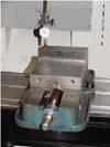
Tip: Use a soft hammer or a champagne hammer to tap the clamp or vise into place. Using a spherical axe or other hard object can damage the fixture.
Make sure that the workpiece is placed in the center of the vise when positioning the workpiece in the milling vise. Most of the workpiece should not be hung from the side of the vise. This can cause the moving jaws to twist the workpiece, thereby greatly reducing the clamping force. If you attempt to drill a hole in a suspended workpiece, the Z-axis thrust may cause the drill point of the workpiece to be pressed down while the other side of the workpiece is lifted. If you need to drill a through hole in a workpiece in a vise, use a stepped jaw. The stepped jaws can be suspended to secure the workpiece and exit the bottom of the vise. This allows a gap to be placed under the workpiece to prevent the vise from being drilled while drilling the through hole. If there are only hard steel jaws and no stepped jaws, use a set of parallel rods in the vise to secure the workpiece away from the bottom of the vise. It is necessary to verify that the parallel bars are the same size to ensure a smooth workpiece setting.
Tip: Most high-precision milling machine visees have keyways and keys on the positioning surface. Since all Haas milling machines are equipped with high-precision T-slots that align with the X-axis, the vise can be positioned in the T-slot using the keys on the vise. This ensures that the vise is perpendicular to the table. If your vise does not have a configuration button, you can use the vise bottom plate (with a key or pin on the bottom) to position the T-slot. At the top, a series of holes can be machined to attach the bottom plate to the machine table, which can be used to attach the vise to the base plate. Position the bottom plate in the T-slot and bolt it to the table. Install a vise on the bottom plate and check the parallelism as described above. Now, each time you use a vise, you only need to position the bottom plate in the T-slot and fix it with bolts. In high-precision machining, it is still necessary to check the parallelism and make small adjustments.
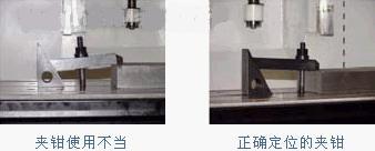
When using a clamp to secure the part by downward pressure, it is necessary to ensure that the clamp is lowered to contact the part and rises when returning. Most down clamps use a screw jack or a serrated block that engages the serrations on the clamp to support the end of the clamp, the end opposite the contact member. The serrated end of the clamp must be higher than the clamp contact end. Otherwise, the clamp will touch the edge of the part, not the top. This greatly reduces the clamping force for the fixed part and may cause a depression at the joint of the top surface of the part and the side. If a screw jack type clamp is used, make sure that the screw jack does not rest directly on the milling machine table. The milling table must be protected with thicker gaskets or other materials. 
Tip: When using clamps in production, the adjustment of the screw jack should be checked regularly to ensure that the end of the clamp screw jack is higher than the contact end. In any case, the fixing bolts should be as close as possible to the workpiece being clamped in order to transmit the maximum clamping pressure.
When it is necessary to clamp the cylindrical surface, it may be best to use a 3-jaw chuck mounted on the machine table.
