Learn the 6 debugging steps of servo motor with Dalan motor
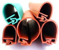
Tailor Made Overhead Line Cover is designed for being applicable to overhead lines and jumper for its voltage range from 380V to 110kV, the function for SINOFUJI Overhead Line Cover is to shorten the safety distance, increase the creepage distance, prevent bird damage, prevent wind deflection, prevent air floating objects and various plants from being collided or contacted, it can be eliminated electromagnetic radiation (induction) Impact on people and animals who are nearby the overhead line.
The servo motor can control the speed and position accuracy very accurately, and can convert the voltage signal into torque and speed to drive the control object. Servo motors can be used in spark machines, robots, precision machines, etc. Usually, as long as there is a power source, and the accuracy requirements are generally related to the servo motor. Before using the servo motor, it must be debugged. The following Dalan motor will lead you to learn about the six debugging steps of the servo motor.
1, initialization parameters
Initialize the parameters before wiring. On the control card: select the control mode; clear the PID parameter; let the default enable signal be turned off when the control card is powered on; save this state to ensure that the control card is in this state when it is powered on again.
On the servo motor: set the control mode; set the enable by external control; the gear ratio of the encoder signal output; set the proportional relationship between the control signal and the motor speed. In general, it is recommended to make the maximum design speed in the servo operation correspond to the 9V control voltage.
2, wiring
Power off the control card and connect the signal cable between the control card and the servo. The following lines must be connected: the analog output line of the control card, the enable signal line, and the encoder signal line for the servo output. After reviewing the wiring without errors, the servo motor and control card (and PC) are powered. At this point, the motor should not move, and it can be easily rotated with an external force. If not, check the setting and wiring of the enable signal. Rotate the motor with an external force to check whether the control card can correctly detect the change of the motor position, otherwise check the wiring and setting of the encoder signal.
3. Test direction
For a closed-loop control system, if the direction of the feedback signal is incorrect, the consequences must be catastrophic. The servo enable signal is turned on by the control card. This is the servo should be rotated at a lower speed, which is the legendary "zero drift". On the general control card, there will be commands or parameters that suppress zero drift. Use this command or parameter to see if the motor speed and direction can be controlled by this command (parameter). If it is not possible to control, check the parameter settings of the analog wiring and control mode. Confirm that a positive number is given, the motor rotates forward, and the encoder count increases; given a negative number, the motor reverses and the encoder count decreases. Do not use this method if the motor has a load and the stroke is limited. Do not give excessive voltage to the test. It is recommended to be below 1V. If the directions are inconsistent, you can modify the parameters on the control card or motor to make them consistent.
4, suppress zero drift
In the closed-loop control process, the existence of zero drift will have a certain influence on the control effect, and it is best to suppress it. Use the control card or servo to suppress the parameters of zero drift, carefully adjust to make the motor speed approach zero. Since the zero drift itself has a certain randomness, it is not necessary to require the motor speed to be absolutely zero.
5, establish closed-loop control
Once again, the servo enable signal is released through the control card, and a small proportional gain is input on the control card. As for how big the calculation is small, this can only be felt by feeling. If it is not reliable, the minimum allowable input control card is input. value. Turn on the control card and servo enable signals. At this point, the motor should have been able to act roughly in accordance with the motion instructions.
6, adjust the closed loop parameters
Fine-tuning the control parameters to ensure that the motor moves according to the instructions of the control card, this is a must-do work, and this part of the work, more experience, can only be omitted here.
----- Editor-in-Chief: Dalan Oil Pump Motor 02-Procurement Consultant
Copyright http: / (Dalan Motor) Reprint, please indicate the source
Http://news.chinawj.com.cn
Tailor Made Overhead Line Cover
High Voltage Line Protective Cover,Overhead Line Cover Sleeve ,Overhead Line Protective Cover,Overhead Silicone Guard
ShenZhen FUJI Electric Material Co., Ltd , https://www.sinofuji.com
