Machine tool numerical control software structure system
Affected by the historical process of computer and microelectronics science and technology development, the traditional structure mode of CNC machine tools consisting of three major modules: metal cutting machine, servo drive motor and numerical control system has been formed. In recent years, in order to improve the system integration and intelligence of CNC machine tools, after NC and CNC, a new generation of CNC NGC and fully open structure OSA have been proposed. The CNC system tends to be open to multi-machine interconnection compatible with PC architecture. The type system has two forms: one is PC+NC and the other is PC-based. The common feature of these CNC systems is the use of multiple CPUs at the upper and lower levels. The PCs at the upper level have certain openness, while the lower levels often have multiple CPUs. The types are varied and the buses are different. The structure of the CNC system varies widely. There are many different ways of communication, and they are not open and universal. For example, in the current domestic high-end CNC system, some subordinates use multiple MCS-51/96 series 8/16-bit MCUs and dedicated boards; some of them are multi-master 8086/87 systems on SS-Bus. The SS-Bus and the superior PC's ISA bus are bridged by a dedicated data communication board; others use TOKO's 3700 series of dedicated chips. 
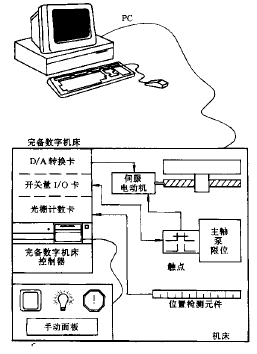
Figure 1 Machine tool numerical control software structure system 1 Machine tool numerical control software structure system and analysis
2 Complete digital machine tools and their controllers

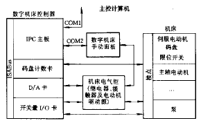
Figure 2 Complete digital machine block diagram 
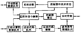
Figure 3 Digital machine tool controller software block diagram 3 application examples
/* set the initial time to zero*/
/* cycle to end time tf*/
/* Calculate the polar angle and increase it evenly over time*/
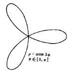
/* Calculate the polar path, according to the equation in Figure 4 / *
/* polar coordinates to Cartesian coordinate conversion / *
/* polar coordinates to Cartesian coordinate conversion / *
/*Tune the send data function*/
/* time increases by one sampling period*/ 
Figure 4 Center trajectory of end mill and its polar coordinate equation 4 Conclusion
