One-time installation of a multi-hole turning jig (figure)
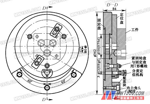
1. Proposal of the problem When processing three holes of a valve body part that is not very large, if you purchase a special machine or CNC machine for this purpose, it will increase the cost of the enterprise and increase the burden on the enterprise. It is not feasible for the general enterprise. Way. If the conventional boring process is used on a common trampoline (first scribe, then calibrated and then boring), the center distance between the hole and the hole is not well controlled (by aligning each hole) control). The diameter of the inner hole is manually adjusted to the length of the tool extension (the length of the tool can only be estimated by experience) and human error occurs when measuring, which makes the dimensional accuracy difficult to guarantee, resulting in low production efficiency. Obviously, with this method, it is impossible to complete the production and processing of a certain number of product parts. If the four-claw single-action chuck is used to clamp the valve body parts on the horizontal lathe for boring (first scribe, then separately according to the position of each hole, respectively), in addition to the ordinary boring machine in the process In addition to the problems that occur during processing, positional accuracy (such as the parallelism between the holes and the holes) is difficult to ensure or even cannot be guaranteed; obviously, it is impossible to complete a certain number of product parts by this method. After the above analysis (the trial product has been used), it is known that the hole machining of the valve body hole system is carried out by a conventional processing method on a horizontal lathe or a boring machine, it is difficult to ensure the processing quality, and it is impossible to complete 600 to 800 pieces per month. production task. To this end, a horizontal lathe boring fixture was designed and manufactured - the secondary installation completes the porous machining fixture, thereby solving the impact on the valve body processing due to factors such as equipment conditions. The fixture enables the workpiece to be installed at one time, and the three-hole system for processing the valve body parts is accurately positioned by the indexing mechanism at three stations, and the diameter of the inner hole can be directly controlled by the middle slide plate when the hole is bored, thereby ensuring The machining accuracy of the valve body hole system and the parallelism between the hole systems. 2. Technology and process analysis The material of the porous valve body is brass H70, and the blank is precision cast (3-16 mm through holes are simultaneously cast during casting). In addition to the three stepped holes, the valve body has been processed. The valve body hole 1, hole 2 and hole 3 are processed in this process. The machining requirements of the valve body parts are shown in Fig. 1. When machining the valve body, a six-point positioning method is employed. The reference surface in contact with the positioning plate limits the movement of the valve body in the y-axis direction, the rotation around the z-axis and the rotation of the x-axis by 3 degrees of freedom; the two positioning pins fixed on the positioning plate restrict the movement of the valve body along the x-axis , rotate around the y axis and move 3 degrees of freedom along the z axis. The clamping method is manually clamped by two M14 bolts fastened to the positioning plate, and the direction of the clamping force is parallel to the direction of the cutting. The processing method of the hole system (3 holes) is: reaming → rough boring → fine boring. 3. The working principle, structure and usage of the fixture (1) Working principle The design principle of the horizontal lathe boring fixture is: the process is concentrated. The positioning of the 3 hole of the valve body part is completed once on the horizontal lathe, which reduces the positioning error and ensures the processing quality of the valve body hole system. The fixture structure is shown in Figure 2. (2) Fixture structure The clamp is mainly composed of two parts. The first part is the fixed plate (as shown in Figure 3), and the fixed plate is directly connected with the flange of the horizontal lathe (C6140). The second part is the positioning plate (as shown in Figure 4). When installing the valve body parts, two of the four processed 11 H8mm through holes on the valve body are mounted on the positioning plate pins, and two M14 double heads are used. Bolt clamping. The center of rotation O1 of the positioning disc and the center of rotation O of the fixed disc do not coincide. The center of rotation of the positioning disc deviates from the center of rotation of the fixed disc by 27.5 mm, and they pass through the cooperation of the 100h6 boss and the 100H7 counterbore. The locating disc can be rotated around its center on the fixed disc and can be screwed onto the fixed disc with three M14 T-bolts. Figure 2 assembly drawing Next page
High-performance microcentrifuge tubes, optimized design, and high-performance quality help protect your samples. Microcentrifuge tubes are made of polypropylene (PP) and are highly mechanically stable, ensuring your samples are stored, run and centrifuged worry-free.
Microcentrifuge tubes have a maximum centrifugation tolerance of 25,000 x g and are autoclavable (20 minutes, 121°C). The centrifuge tube adopts a snap-on tube cover design, which can be operated with one hand and has good sealing performance, which can effectively prevent liquid leakage; the tube wall is smooth, and the tube body is designed with a frosted area for convenient marking.
microcentrifuge tube sizes,microcentrifuge tubes 1.5 ml,microcentrifuge tubes uses Yong Yue Medical Technology(Kunshan) Co.,Ltd , https://www.yongyuecultureflask.com
The washing machine uses tap water to pressurize and clean the object. If the pressure is insufficient, the cleaning effect is not achieved. In order to withstand a certain amount of pressure, there are strict requirements in the design and manufacture of each part. The valve body is a very critical part of the washing machine (as shown in Figure 1). In particular, the machining dimensional accuracy and positional accuracy of the three holes in the valve body part are directly related to the performance and service life of the washing machine. Therefore, processing must be carried out in strict accordance with the requirements of the drawings. 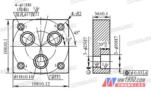
Figure 1 valve body