Research on High Speed ​​Machining Tool Technology

The high-speed machining that represents the mainstream of modern machining has been rapidly developed in response to the demands of high efficiency, high precision, flexibility and greenness in the 21st century. The biggest feature of high-speed machining is that it greatly satisfies high-efficiency production and greatly improves the machining accuracy and surface quality of the machined parts. Using the "one-off" technology of high-speed machining, the traditional rough finishing can be completed in one time, which can obtain high-quality machining surface and save the traditional process, which greatly improves the processing efficiency. With the universal application of electric spindles in machine tools, the factors that restrict the cutting speed of machine tools are not only the machine tool spindle itself, but also the research on tool systems and technologies suitable for high-speed machining has become an important factor affecting the continuous development of high-speed machining. Therefore, it is of great significance to study the new requirements of high-speed machining on the tool system and develop a tool system suitable for high-speed machining. In view of the shortcomings of traditional tools in high-speed machining, based on the careful analysis of the requirements of high-speed machining on the tool system, the technical methods of the tool system suitable for high-speed machining are discussed.

1 High-speed machining to the requirements of the system

High-speed machining is not only the increase of the spindle speed, but the shortening of the overall machining time. Therefore, high-speed machining requires not only high rigidity, safety, flexibility, dynamic balance and ease of operation, but also the rigidity and accuracy of the connection between the tool system and the machine tool, and the clamping force of the tool holder to the tool. Clamping accuracy and the like all put forward high requirements.
The so-called tool system is a complete tool system consisting of a clamping tool holder and a cutting tool. The clamping tool holder is matched with the machine tool interface, and the cutting tool directly processes the machined part, both of which are extremely important. High-speed cutting tool systems must meet the following requirements:
  1. High safety of the tool structure As a tool system for high-speed machining, the structure must be highly secure to prevent the blade from flying out when the tool rotates at high speed, and to ensure that the rotating blade does not break at twice the maximum speed.
  2. Excellent dynamic balance of the tooling system The dynamic balancing of the tooling system for high-speed machining is critical. According to the knowledge of theoretical mechanics, the centrifugal force F= mr w 2 , when the dynamic balance performance of the tool system is poor, the high-speed rotating tool will generate a large centrifugal force, which will cause the tool bar to bend and generate vibration, and the result will be the machined parts. The quality is reduced and even the tool is damaged.
  3. High system rigidity The static and dynamic rigidity of the tool system is an important factor affecting the machining accuracy and cutting performance. Insufficient rigidity of the tool system will cause the tool system to vibrate or tilt, resulting in reduced machining accuracy and machining efficiency. At the same time, system vibrations can increase tool wear and reduce tool and machine life.
  4. High system accuracy System accuracy includes system positioning clamping accuracy and tool repeat positioning accuracy as well as good precision retention. The tool system with the above accuracy requirements can guarantee the static and dynamic stability of the whole system at high speed, thus meeting the requirements of high speed and high precision workpieces.
  5. High interchangeability For modular tool systems, the tool system needs to be more flexible in order to adapt quickly to the machining needs of different parts by adjustment or assembly. In addition, the tool and machine interface should use the same tool holder system to reduce unnecessary inventory.
  6. Efficient tooling systems must have high-quality, long-life tools to meet the requirements of high-speed and efficient machining of workpieces.
  7. Highly adaptable The tooling system should have the ability to machine a wide range of hardness materials to meet the requirements of high speed machining of various workpieces.

2 Problems with traditional tool systems

  1. Low tool positioning accuracy and repeat positioning accuracy During high -speed machining, the spindle taper hole and the tool taper shank are radially expanded due to the centrifugal force. When the amount of expansion of the taper shank is smaller than the amount of expansion of the taper of the main shaft, a fitting gap occurs. Therefore, under the action of tightening the tension of the screw, the taper shank drives the axial displacement of the tool, which causes the axial positioning accuracy of the tool to decrease when the tool is added at a high speed.
    Simultaneously. The shank and the spindle taper are only connected by a tapered surface, and the axial rigidity is low, resulting in low repeatability of the tool.
  2. Tool dynamics and static stiffness are low. When the tool rotates at high speed, the difference in the axial expansion of the spindle taper under the centrifugal force makes the stiffness of the low-rigid joint originally combined by the cone surface further reduced.
  3. The long taper of the shank is not conducive to rapid tool change and miniaturization of the machine tool spindle.
Due to the above reasons, the traditional tool system can not meet the needs of high-speed machining, and it is necessary to research and develop a tool system suitable for high-speed machining.

3 Tool technology based on high speed machining
  1. Tool material technology
  2. The main requirements for high-speed machining are: high temperature chemical properties, thermophysical properties, chemical stability, coating crack resistance, adhesion resistance and thermal shock resistance. High-speed cutting tool materials must be selected according to the material and processing characteristics of the workpiece to be processed, and with reasonable cutting conditions, in order to achieve excellent cutting performance. For ferrous metals such as steel and cast iron, ceramics, cermets and cubic boron nitride tools should be used. For non-ferrous metals such as aluminum and magnesium, tool materials such as PCD and CVD should be used. At present, in the US aerospace industry, the cutting speed of milling aluminum alloy has reached 7,500 m / min, and its cutting speed is mainly limited by the spindle speed of the machine tool. For ferrous metals such as steel and cast iron, the cutting speed achieved in high-speed cutting is 1/3 to 1/5 of the processed aluminum alloy, which is about 1,000 to 1,200 m/min, and the speed is mainly limited by the heat resistance of the tool material. The goal of high-speed cutting in the future is to cut the aluminum alloy at a cutting speed of 10,000 m/min. Cast iron is 5,000m/min, ordinary steel is 2,500m/min, and aluminum alloy, cast iron and ordinary steel are drilled at speeds of 30,000m/in, 20,000m/min and 10,000m/min, and high-speed and ultra-high-speed machining in the future. Tool materials such as superhard tool materials (such as PCD, PCBN), ceramic tools, coated tools, and TiC(N) based carbide tools will play an important role.
  3. Knife system interface technology
    Tool system interface technology includes tool-machine interface technology and tool-tool interface technology.
    1. Tool-machine interface technology
      In order to overcome the adverse effects caused by the traditional shank only relying on the taper positioning, some scientific research institutions and tool manufacturers have developed a new type of connection method that enables the shank to simultaneously position the conical surface and end surface of the main bore of the main shaft—two-sided constrained over-positioning Clamping system. The system has high contact stiffness and repeatability and reliable clamping. At present, the system mainly has two forms: a short taper shank and a 7:24 long taper shank. Although the 7:24 taper shank is interchangeable with the traditional BT shank and can be easily mounted on a machine with a taper taper of 7:24, it can improve the rigidity and accuracy of the connection between the shank and the spindle, but from the cutting. In view of the trend of high-speed machining with increasing speed, the development of the shank structure of the short taper shank with a taper of 1:10 is more promising. At present, the two-sided constraining shank of the short taper shank mainly includes HSK, KM, NT, BIG-PLUS and the like.

      1
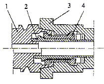
      1. Shank 2. Pull rod 3. Spindle 4. Spring sleeve
      figure 1
      1

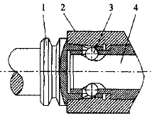
      1. Shank handle 2. Pull rod 3. Lock steel ball 4. Locking rod
      figure 2

      1
      image 3

      The taper shank part of the HSK holder adopts a hollow short taper shank with a taper of 1:10, and its structure is shown in Fig. 1. When the shank is connected to the main shaft, it is centered in the taper hole of the main shaft by means of a short taper shank. When the short taper shank is in close contact with the spindle taper hole. There is a gap of about 0.1 between the end faces. Under the action of the tensioning force, the gap is compensated by the elastic deformation of the hollow shank to achieve the two-dimensional constrained positioning with the tapered surface of the main shaft and the end face. At this time, the interference between the short shank and the spindle taper hole is about 3 to 10 μm. Since the hollow shank has a large elastic deformation, the manufacturing precision of the shank is relatively low. In addition, due to the short handle and small mass of the HSK tool system, it is beneficial to automatic tool change and miniaturization of machine tools. However, the short hollow taper shank structure also affects the stiffness and strength of the system. HSK tool holders are available in A, B, C, D, E and other forms. The limit speeds of HSK40A, HSK40E and HSK63E can reach 4,200r/min, 5,5000r/min and 3,2500r/min.
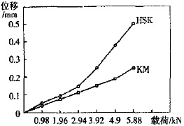
      KM (Kennametal) module system researched and developed by Kenner Company of the United States - double-sided clamping tool system, its structure is shown in Figure 2. It uses a three-point positioning method for both lathes and turning centers and machining centers. Due to its unique structure, high speed, high rigidity and high precision, it is being adopted by more and more machine tool manufacturers. Compared with the HSK tool holder, the interference between the KM tool holder and the spindle taper hole is about 2 to 5 times higher. For example, the KM6350 (equivalent to BT40) has an interference of 10 to 25 μm. In practical applications, KM6350 and KM4032 The rotational speeds reached 36,000 r/min and 50,000 r/min, respectively. The stiffness comparison between the HSK and KM systems is shown in Figure 3.
      The BIG-PLUS tooling system adopts a 7:24 taper. Its structural design ensures that the clearance between the spindle and the spindle end face is about 0.2. When locking, the clearance can be compensated by the elastic expansion of the inner bore of the spindle to ensure the shank and The end face of the spindle is tight.
      The two-sided restraint clamping system makes up for many of the shortcomings of the traditional tool system, and represents the mainstream direction of the tool-machine interface technology, which will surely become more and more widely used. At present, foreign countries have developed a two-sided restraint clamping system of various structural forms. Because of its series of advantages such as high repeatability and high dynamic and static stiffness, the system can meet the requirements of high-speed machining.
    2. Tool-handle interface technology
      The clamping force of the tool holder and the clamping accuracy are very important in high-speed cutting. If the tool holder is not firmly clamped to the tool, the machining accuracy is reduced, and the tool and the workpiece are damaged, and even a safety accident is caused.
      To improve the clamping accuracy of the tool system, we must try to make the tool accurately and reliably positioned to ensure sufficient clamping force, we must strictly control and improve the tooling system precision, increase the clamping length, optimize the structural design and rational material selection. At present, there are mainly the following types of tool chucks suitable for high-speed machining:
      1. Heat shrink chucks The tool holders are used for thermal expansion and contraction to ensure reliable tool clamping. It is a chuck without clamping elements, which is simple in structure and large in clamping force.
      2. High-precision spring collet The high-precision collet chuck manufactured by Japan's Dazhao Seiki Co., Ltd. uses a taper angle 12° taper sleeve, and all the chucks are balanced and trimmed to meet the requirements of high-speed machining. At present, the speed of such a chuck can reach 30,000 to 40,000 r/min.
      3. High-precision hydraulic chuck The high- precision hydraulic chuck of the BlG-PLUS tooling system is a two-point clamping integrated construction with high clamping force and clamping accuracy and reduces the quality of the chuck.
      4. The high-precision hydrostatic expansion chuck is a high-precision hydrostatic expansion chuck produced by the German company, and the oil pressure in the oil chamber is increased by tightening the pressure bolt, so that the inner wall of the oil chamber is uniformly symmetrical and axially expanded. Clamp the tool. The chuck has a very high clamping accuracy and its radial runout is less than 3 μm.
      5. Triangular deformation chuck The chuck clamps the cutter by the deformation force of the chuck itself, and its free state is a triangular shape. When the cutter is clamped, the inner hole of the chuck is rounded by the hydraulic force, and the external force is removed. The inner bore is re-contracted into a triangular shape to achieve three-point clamping of the tool. The chuck has a compact structure, high positioning accuracy (up to 3 μm or less) and symmetry, and simple tool clamping.
      6. The new structural chuck is powered by Sandvik's new Coro Grip collet, which is hydraulically driven to push the taper sleeve and is measured at 3D with a radial runout of 2 to 6 μm. This chuck is more reliable and has a high rigidity. For hydraulic chucks, the clamping time is shorter than the heat shrink chuck. The new clamping method of the cylindrical shank introduced by ISCAR not only ensures end contact, but also forms clamping force on half of the circumferential surface, which improves the clamping rigidity.
  • Tool balancing technology
    High-speed machining places high demands on the dynamic balancing technology of the tool. In general, the milling cutter holder—the spring collet can be balanced by balancing. For example, the high-balance heat shrink chucks (SK3, SK4~6) introduced by NT Corporation of Japan can reach 70,000r/min, and SR10~20 can reach 50,000r/min. For the fine boring head with fine adjustment mechanism, in order to balance the change of the center of gravity when the machining diameter is adjusted, Japan's Dazhao Seiki Co., Ltd. has introduced a hoe-EWB that can be used for automatic balance compensation, for machining apertures of Ø32-105 and Ø2 ~ Ø42 high-speed fine boring head EWB32 ~ 105 and EWB2 ~ 50, its cutting speed of up to 20,000r / min.
  • 4 Tool design technology

    High-speed cutting tool design techniques include optimization of tool geometry parameters, tool-safe structure design, and blade clamping mechanism design.
    The main features of high-speed cutting tool damage are: hot wear of the tool tip and breakage of the notch at the cutting edge of the tool. Therefore, the rake angle for high-speed machining tools should be smaller than that of ordinary tools ( g ≤ 0°), the back angle should be larger than that of ordinary tools (5° to 8°), and the round and sharp edges should be used at the joints of the primary and secondary cutting edges. Or chamfering the tip to increase tool rigidity and reduce the probability of cutting tool breakage.
    The tool structure design should be based on the material to be machined and the process to optimize the combination of tool material, coating and groove function to develop the blade structure with the best cutting effect. For example, the multi-functional inserts introduced by ISCAR and Mitsubishi have the space cutting edge and curved rake face, the cutting force is small, the cutting edge strength is high, and the anti-wear ability is high during high-speed machining. It can be said that the cutting edge structure of high-speed machining cutting tool .
    In addition, the tool clamping structure should also be adapted to high-speed machining requirements, such as the use of a new blade clamping structure to prevent the blade from flying out, the small body weight and light design, the highest limit speed and the blade clamping torque.

    5 Conclusion

    High-speed machining has become the mainstream development direction of mechanical manufacturing. Therefore, research on tool system technology suitable for high-speed machining is of great significance. With the development of advanced manufacturing technology and material technology and nanotechnology, new multi-component, composite, nano-scale hard coatings and functional materials such as CVD diamond films, super-hard tool materials, ceramic tools, coated tools, etc. will be widely Application, high-speed cutting tool system will become more and more perfect, and become an important part of promoting high-speed cutting.
    Original: Mechanical Engineer, No. 2, 2003

    Brass Shower Holder

    Material: Solid Brass
    Color: Chrome
    Function: Hand Shower Holder with G1/2" Screw Connecting
    Usage: Shower
    Water Pressure: Working Pressure: 0.05-0.8Mpa, Recommend Pressure: 0.1-0.5Mpa, Nominal Pressure:0.6Mpz
    Water Temperature: ≤90°c
    Installation Type: Wall Mounted, G1/2"
    Plating: Nickle (7.5-9.5um), Chrome (0.25-0.45um). Shining permanently
    Acidity Test: >12 hours, corrosion status comply with international standard, anti-oxidation, anti-rust spot
    Salt Mist Test: ASS 24 hours Salt Mist Test, corrosion status comply with international standard
    Size: G1/2"
    Standards: CE, ACS, Watermark
    Warranty: 5 years


    Brass Shower Holder,Brass Hand Shower Holders,Brass Bathroom Shower Holder,Brass Shower Holder With Spout

    KaiPing HuiPu Shower Metalwork Industrial CO,LTD , https://www.hp-shower.com