Creep rupture
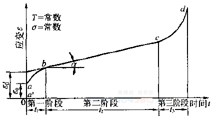
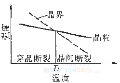
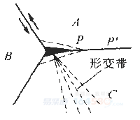
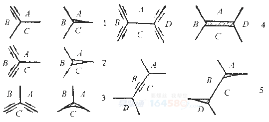
Creep can occur under any stress conditions ranging from absolute zero to melting point. The most common creep in engineering is the long-term operation of parts at 0.5Tm (the melting point expressed in absolute temperature), such as aero engines, boilers, steam turbines, and chemical equipment. Therefore, the so-called creep refers to this type. However, carbon steel parts operating at temperatures above 300 °C and alloy steel parts operating at around 400 °C must take into account the effects of creep. The creep phenomenon mentioned below in this section refers to high temperature creep. A typical creep process is shown in Figure 9-19. In the figure, the ab segment is the first stage of creep, also called the deceleration creep phase. In this segment, the pulp time is prolonged, the creep velocity is reduced, and the creep velocity to the b point reaches the minimum value. The bc segment is the second stage of the creeping creep phase of creep, in which the creep rate remains almost unchanged. Generally speaking, the creep speed refers to the deformation speed at this stage. The third stage cd is the accelerated creep stage. As time goes by, the creep speed gradually increases until the creep point occurs at point d. The macroscopic feature of the creep fracture is obvious plastic deformation near the fracture. There are many cracks on the fracture surface, and the surface is covered by an oxide film. The microscopic feature of the creep fracture is that when the part is operated above the TE temperature, the fracture of the metal is a grain-like fracture, and below the TE is a transgranular fracture. TE is a temperature at which the grain temperature is equal to the grain boundary strength at the same temperature. The creep along the crystal duct fracture is sugar-like, with a thick layer of oxide on the fracture surface, and sometimes chopped patterns are visible on the fracture. Figure 9-20 is a schematic diagram of the strong temperature such as creep. When the temperature increases, the grain strength and grain boundary strength decrease, but the grain boundary strength decreases rapidly. Creep has two forms of intergranular fracture, one is a wedge-shaped creep crack and the other is a cave-type creep crack. Wedge cracks occur at low temperatures, high stresses, and high creep rates. Cracks usually originate from the triangular grain boundaries and then expand along the grain boundaries as shown in Figure 9-21. The formation mechanism of the wedge-shaped crack is that during the creep deformation process, when the grain boundaries of the A and B grains are relatively slipped, the deformation zone in the C grain is inconsistent with the grain boundary slip of the A and B grains. Therefore, stress concentration occurs at the intersection of the three grains of A, B, and C. When the stress exceeds the grain boundary bonding force, a wedge crack source is generated. Under the action of external force, the crack propagates along the grain boundary perpendicular to the external force, and many of these micro-cracks are connected to each other to form a brittle edge along the crystal. Figure 9-22 is a schematic diagram of various wedge-shaped crack formations under different grain boundary slip conditions. The fracture caused by the wedge-shaped crack has a smooth grain boundary, and sometimes the grain boundary sliding step can be seen, and the edge of the grain boundary is clear. Hole-shaped cracks: At higher temperatures, lower stresses, and lower strain rates, hole-shaped cracks are generally formed at grain boundaries. The formation mechanism of the cavity crack is due to grain boundary slip, and protrusions or steps are often generated in the grain boundary perpendicular to the direction of the pull, thereby forming a cavity crack source, as shown in Fig. 9-23. If there is a second phase on the grain boundary, since the grain boundary slip is hindered, a stress concentration crack occurs at the interface between the second phase and the substrate, and a void source is also formed. Many voids formed on the grain boundaries grow and are connected to each other, causing creep rupture. The fracture caused by the cavity crack has many holes in the fracture surface. The well has many spherical precipitates, and the edge of the grain boundary is not sharp, as shown in Figure 9-24. Led Motif Light Outdoor,Led Sculpture Motif Light,Christmas Rope Light Motifs Tianjin Jinji Optoelectronic Technology Co., Ltd. , https://www.tjjjgd.com