Plastic pipe chipless cutting machine design
Application Technology Plastic Pipe Material Chipless Cutting Machine Design Liu Junping (School of Mechanical Engineering, Taiyuan University of Technology, Taiyuan 030024, China) The problem that the tool holder should be rotated and flattened, and the determination of the angle of the chute is discussed in detail, and finally the chute The determination of the angle makes reasonable suggestions. : Plastic pipe; chipless cutting; force analysis Plastic pipe with its superior characteristics, more and more widely used in construction engineering, municipal engineering, urban gas pipe network and other fields, gradually replaced the traditional metal pipe. Since the plastic pipe is connected during the use process, the quality requirements of the shear section are also higher and higher, and the section is smooth and flat, and there is no burr. This is actually a higher requirement for the pipe shearing equipment. The conventional sawing machine uses a circular saw blade with a tooth to perform sawing, which has a rough section, a large amount of sawdust and a large noise. The chipless cutting adopts a pair of toothless circular cutter discs. After cutting, the product has a clean and smooth section, no noise and no debris, which greatly improves the cutting quality and improves the working environment. It is a promising pipe cutting equipment. It is currently being used more and more for the cutting of pipes. 1 Working principle of the chipless cutting machine The section of the plastic pipe is ring-shaped and is continuously extruded. This requires cutting in the movement. The blade should first move synchronously with the pipe, and the cutter should be rotated around the pipe and fed. . See the principle of motion. According to the above principle, the chipless cutting machine is composed of the following parts: the rotating device drives the cutter to rotate around the pipe; the feeding device realizes the radial feeding while rotating the cutter; the follower device should ensure the synchronous movement of the cutter and the pipe; The clamping device tightens the pipe at both ends during cutting to ensure stable cutting. 2Proposed and analyzed of chipless cutting To complete the chipless cutting process, the key problem that must be solved is to realize the cutter head relative to the pipe in the structure, which is relatively static along the axial direction, and enters the blade in the radial direction. The pipe is rotated. The follow-up of the cutter head is realized by moving the movable frame relative to the fixed frame, and the rotating device, the feeding device and the tightening device are all mounted on the movable frame, and the movable frame is driven by the chain, and the moving speed and the moving frame of the movable frame are driven. The same speed of the pipe is produced, which solves the problem that the cutter head and the pipe are relatively stationary. The feed motion is driven by the feed cylinder to linearly move the U-shaped frame with 30 slots, and the axial movement of the cylinder is converted into the radial feed motion of the cutter disc by the action of the chute. The rotation of the cutter coil around the pipe is driven by the motor to drive the pinion, and the drive gear is further driven by the cutter. 3 Plastic pipe material chip cutting machine design scheme page 55 is the proposed cutting assembly drawing, due to structural symmetry, the author only shows half in the explanation. Cutting process: the transmission gear drives the hollow shaft to make a rotary motion. At the same time, under the action of the thrust of the feed cylinder, the horizontal thrust disc moves horizontally relative to the movable frame, and the thrust is transmitted to the rotary thrust disc through the thrust bearing, and then The force is transmitted to a pair of U-shaped inclined trough frames. The angle of the chute on the U-shaped chute is 30, and the upper and lower pair of nylon sleeves are integrally connected with the guide rails, and the horizontal axial movement is converted into a guide rail along the slider. The radial infeed motion, and the cutter head is integrally connected with the guide rail, and a pair of blades simultaneously press the pipe into the knife and rotate around the pipe to complete the cutting. When the entire cutting device hits the stroke switch, the cylinder drives the pullback plate to quickly reset the entire device to prepare for the next cutting process. Feeding and rotating devices are an important part of this design. The middle moving member has four kinds of motion states: the horizontal thrust plate only performs translation; the rotary thrust plate and the U-shaped inclined groove frame both perform translation and rotation; the cutter holder is connected with the guide rail, and also rotates while rotating. The rotary thrust disk and the barrel only perform the rotary motion. The horizontal thrust disc and the rotary thrust disc should be kept in contact at all times. When cutting, the cylinder transmits the axial thrust to feed the cutter disc. After the cutting, the cylinder pulls the U-shaped frame back to complete the reset. At the same time, the rotary thrust disk rotates relative to the horizontal thrust disk to realize the rotation of the tool holder. Here, a thrust bearing is arranged to solve this problem. In addition, there is relative rotation between the rotary bearing plate and the movable frame, and a thrust bearing is also provided between the two to transmit the axial force to the movable frame. 4 design of the infeed device The working principle of the infeed device is to transform the axial movement of the infeed cylinder into the radial movement of the knife, and the key to achieve this movement is to rely on the U-shaped chute and two pairs of linear guides to complete ,see. The guide rail A is fixed to the rotary thrust disc, and the slider A is fixed to the U-shaped chute bracket, and the initial position of the U-shaped chute bracket is adjusted according to the wall thickness of the cut pipe and by screws. The slider B is fixed with the rotary bearing plate, the front end of the guide rail B is fixed with the cutting disc cutter, the rear end is fixed with the thrust block, and the thrust block is formed by a pair of cutter head assemblies for the nylon sleeve and the pin shaft. Along the 30 chute movement of the U-shaped chute, when the feed cylinder moves to the right, due to the action of the chute, the cutter disc assembly is forced to feed along the radial direction of the slider B toward the center of the pipe to perform cutting. When the cutting is completed, the infeed cylinder pulls the U-shaped chute to the left, and the cutter disc leaves the pipe along the guide B, waiting for the second cutting. 1—rail A; 2—slider A; 3—adjustment screw; 4—U-shaped chute frame; 5—rail B; 6—slider B; 7—pin; 8—nylon sleeve; 9 thrust block feed The structure diagram of the device shows that the chute on the U-shaped chute has the function of direction and force conversion, which converts the axial force applied by the cylinder into the required cutting force of the guide rail B, and correspondingly completes the movement direction. change. The following two issues are mainly considered when designing the angle of the chute. The angle of the chute should be such that the overall structure is compact. As can be seen from page 56, when the angle is small, the length of the entire device becomes larger and the width becomes narrower. The angle of the anti-swash plate increases, the length of the device becomes shorter, and the width becomes wider. Considering the thin wall thickness of the plastic pipe, the required feed stroke is not large, and a smaller swash plate angle should be selected. The thrust of the cylinder should be as small as possible. The thrust P of the cylinder is to provide power for the blade feed. The resistance of the feed mainly includes the force required to cut the pipe, the friction between the guide rail and the slider, etc. The magnitude of this resistance is substantially fixed under certain conditions. In order to provide the cylinder with technological innovation and productivity, P is the thrust of the cylinder; F is the friction between the swash plate and the connecting bolt of the slider; N is the positive pressure of the feeding device to the chute; fN is the inclination of the feeding device The friction of the groove; a is the angle between the chute and the horizontal line; p is the friction angle. Considering the lubrication condition at the contact, the positive pressure and friction at the contact are combined into a force R, a clamp between R and N. The angle is the friction angle p, so that the oblique slider is subjected to three forces to maintain balance. According to the triangular rule of force, it can be concluded that the relationship between P and R is that the guide rail (1) is connected with the tool holder, and the force is seen. The O point is the center of the rotating pair, and T is the cutting time. The sum of the resistance of the feed and the friction between the guide rail and the slider, the moment of the O point is obtained, h/r is about 1.5, the relationship between the cylinder thrust and the sawing resistance and the angle of the chute in Table 1 is concluded by the plastic The meticulous research and design of the pipe-free chip cutting machine systematically masters its working principle and corresponding structural design. For a few complex movements, corresponding measures are taken to meet the actual requirements, and at the same time, from the overall consideration of the equipment, The main parts are subjected to force analysis, and reasonable suggestions are made for the determination of the angle of the chute, which can be used as reference for the design of similar equipment.
Advantages of LED Grow Light for weed.
Available weed grow lights.
C Series led Grow Light : cob 600w 1200w 2000w 3000W LED Grow Light, with advanced cob technology, focusing lighting, ensure high ppfd. And this series led grow lights are with veg bloom switches, you could change spectrum from seeding to flowering. And they are daisy chained. easy to use and install.
G series led grow light: G110w G220w led grow light. This series led grow lights are with compact shape, suitable for small space. But they are powerful with samsung leds and reflector. and it's waterproof.
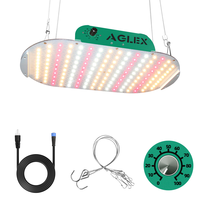
K series led grow light: K1000 K2000 K4000 led grow light, with dimmer. Freely to adjust lighting intensity according plants needs. when seedling, turn dowm it, when flowering, turn up. And down at night, up at noon. Very convenient. The K4000 with a specially design, it can be fold up. easy to carry and install.
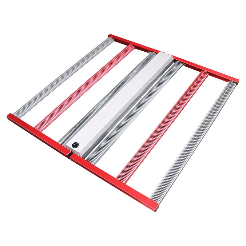
L series led grow light: 700w led grow light is a decent light, foldable and dimmable and you could add controller. 700w powerful led grow light is great for weed. PPE 2.8-3.0 μmol/J. Spider grow light design can delivery uniform light, great for weed growing.
M series led grow light: 240w 320w 400w 600W LED Grow Light. This series led grow light is like L700 with dimmer and foldable. They also with spider design. but it with external driver. So you could put driver out of tent, ensure lower heat and easy to control.
If you want to see more, please contact us for details.
Weed LED Grow Light, Herb Grow Light, Grow Light for Seed Starting, Seedling Grow Light, Grow Light for Seedlings Shenzhen Ameri Technology Co., Ltd. , https://www.aglexz.com


