Tool design method based on UG NX
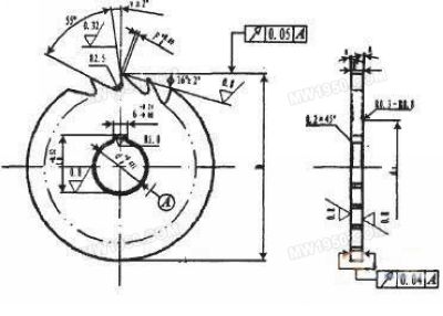
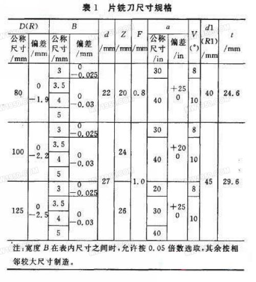
In the process of product design and development, standardization, generalization and serialization of components are effective ways to improve product design quality and shorten product development cycle. Parametric design based on 3D CAD system can meet the requirements of 2D drawing. Manufacturing information requirements. The emergence of parametric technology is an important revolution in the development of CAD technology. The technology is based on constrained modeling, allowing engineers to modify the design results in a size-driven manner, which is ideal for serialized product designs with similar structures. In this paper, UG NX is selected as the support platform, and the company's factory standard milling cutter is taken as an example to study the realization methods and methods of parametric design. Other tools are designed in a similar way. The tools used in CNC machine tools and machining centers (referred to as CNC tools) have developed rapidly in foreign countries, and the varieties and specifications have formed a series. China's research and development of CNC tools started late, and the development and production of CNC tools has become a weak link in China's tool industry. The backwardness of CNC tools has become one of the main obstacles affecting the full play of domestic and imported CNC machine tools. At present, the way to design CNC tools abroad is basically to form new varieties or specifications by directly calling existing design results or partially modifying them. Domestic enterprises (including China's first automobile manufacturing plant) are mostly interactive drawing by designers on the CAD (mostly AutoCAD) software platform in CNC tool design. Because interactive drawing is difficult to use existing design results, labor intensity is high, design efficiency is low, and it is difficult to meet actual production needs. Therefore, research and development of advanced CNC tool CAD/CAM technology is necessary to improve the quality and efficiency of CNC tool design and manufacturing. Parametric technology is based on constrained modeling, allowing engineers to modify the design results in a size-driven manner, which is ideal for serialized product designs with similar structures. UG NX is the CAD/CAE/CAM integrated software of EDS Company of the United States. It has powerful parametric design functions and has been widely used in design and manufacturing. This paper takes UG NX as the supporting platform and takes the company's chip milling cutter as an example to study the realization methods and methods of parametric design. The design method of other CNC tools is similar. 1 parametric design ideas When using UG software for product design, in order to give full play to the design advantages of software, we should first carefully analyze the structure of the product, conceive the relationship between the various parts of the product in the brain, fully understand the design intent, and then use the powerful UG to provide Design and editing tools reflect design intent into the design of the product. Because design is a very complicated mental activity, a design from the task to the completion of design will never be smooth, the completion of a design is a process of continuous improvement, continuous improvement, therefore, in this sense The design process is the process of modification. The purpose of parametric design is to make flexible modifications according to the design intent of the product, so its easy modification is crucial. This is why UG software emphasizes its powerful editing features. UG tool parametric design idea: the construction work of the tool part model is divided into four basic tasks: geometric constraint, size constraint, size determination and model generation. Model generation is a huge, trivial but regular work, which can be done by computer based on 3D software such as UG; shape constraint, size constraint and size value determination are irregular creative work, designed by designers according to design requirements. Determine and establish the dimensional association between the feature of the part. When the user modifies the part model, he only needs to input a new set of feature size values, or individual size values, and change the part structure without redesigning. Some characteristic parameters can be used. The product model of the chip milling cutter should include blades, shanks, clamping devices, etc. During the design process, the tool components are described in the form of geometric shapes. The geometry that makes up each part of the face milling cutter consists of structural constraints, pixel sets, and parameter sets. A pixel set is the basic geometric element that makes up a geometry, such as points, line segments, arcs, polygons, and so on. In order to improve the efficiency of the software, closed polygons are often used to define the geometry to reduce the number of pixels. Structural constraints are used to define the structure of a geometry, such as the concentricity of two circles, adjacent edges being perpendicular or parallel to each other; the parameter set is used to determine the size of the geometry, such as the length of the line, the radius of the circle (arc), and so on. And the positional relationship between each geometry is expressed by the same parameters between the parameter sets. 2 3D parametric modeling implementation method The following describes the parametric modeling method by creating an example of the 3D model of the company's factory-standard tool CRB153-2001. 2.1 Analyze the part model to set the characteristic parameters As shown in Figure 1 and Table 1, the main dimensions of the chip milling cutter are R, Z, B, d, R1, a, F, v, t. These 9 dimensions can be used as the main parameters to drive the die cutter model. The model of the chip milling cutter can be obtained by modeling such as stretching, array, rotation, etc., and special attention should be paid to the characteristic parameters and their relationship when modeling. Figure 1 Piece of iron knife indicator circle 2.2 Drawing sketches and size constraints UG NX has a complete automatic extraction of system parameters. It can save the input size constraints as feature parameters in the sketch design, and visually modify them in the subsequent design to reach the most direct parameter-driven modeling. purpose. The key to driving graphics with system parameters is how to convert the parameters extracted from the physical objects into UG to control the characteristic parameters of the 3D model. Size drive is the basis of parameter drive, and size constraints are the prerequisite for size drive. The size constraint of UG is characterized by the combination of shape and size, and the control of the geometry is achieved by dimensional constraints. The design must be based on a complete size reference (full constraint), not missing or multi-note size. The size driver is implemented in the 2D sketch Stretcher. When the shape of the sketch in the sketch is determined relative to the coordinate axis position, the shape and position relationship can be changed cooperatively after the graphic is completely constrained, and the system will directly convert the size constraint into the system parameter. Roofing/Heating/welding torches Long Handle Heating Torch,BBQ LPG Flame Gun,Wholesale Long Gas Torch Shangqiu Zhengtu Hardware Technology Co,.Ltd , https://www.ztlighter.com

Previous page 1 2 3 Next page
